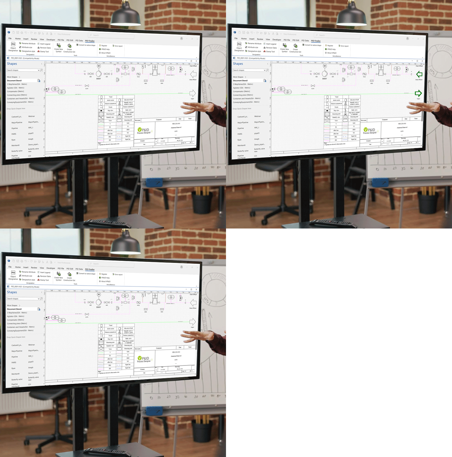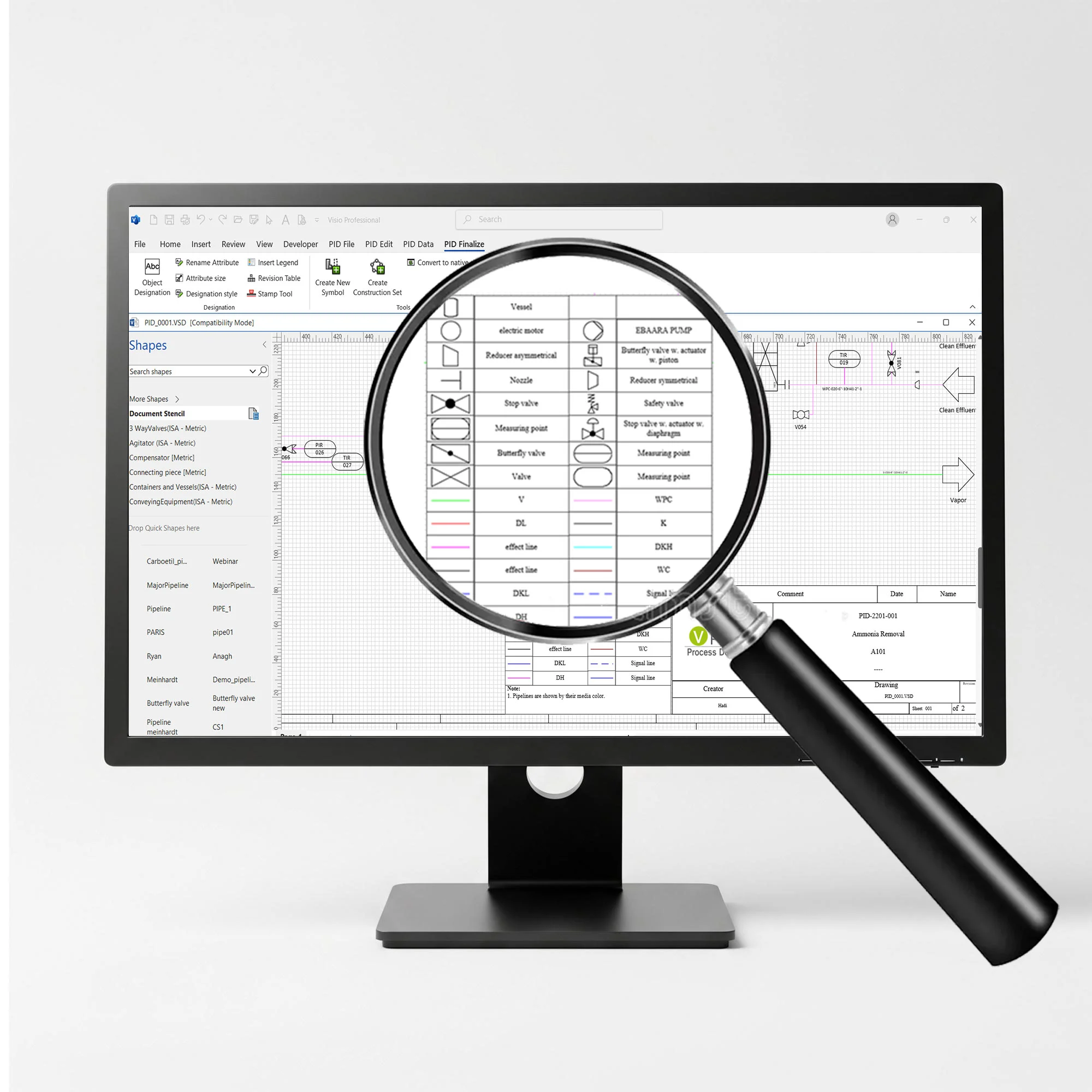
Leveraging the power of Visio®-based easy functionalities & object-oriented database technology for creating smart & quick P&ID’s

Visio P&ID Process Designer is a solution that extends Microsoft Visio® with object-oriented database technology for creating intelligent Piping & Instrumentation Diagrams (P&IDs) and Process Flow Diagrams (PFDs).

The solution converts conventional drawings into structured, data-driven engineering documents by integrating intelligent symbols, specification-driven pipelines, automated tagging, revision management, and report generation within the familiar Visio environment.

It improves engineering accuracy, ensures standardization, and increases productivity across the entire lifecycle of plant and process design projects.

Key Features of Visio® P&ID Process Designer

Create your own Symbols/Libraries

Industry Standard P&ID Symbols / Libraries

  • Intelligent standard libraries (ANSI, ISO 10628, IEC 62424, ISA-5.1) and dynamic symbols with associated attributes and relationships
  • All symbols and drawing elements have associated data properties (e.g. media, piping class, material, pressure, temperature)
  • Spec. Driven Pipelines (PN10, PN16, PN40, LBS150, LBS300)
  • Create your own Symbols/Libraries

  • Visio® P&ID Process Designer’s built-in ‘Create New Symbol’ allows users to create their own symbol and save it in shapes stencils
  • It also allows easy creation of sub-assemblies of components using construction set feature. You can save sub-assemblies in the shapes stencil and reuse it at later stage
  • Each component within construction set has associated data properties. For e.g. a pump group will have pump information, valve data, Instrumentation details
  • Alt Text

    Cross References

    Cross reference in a Drawing enables users to continue process diagram of single systems across multiple drawings. Cross references added in Visio® P&ID Process Designer not only provide the information (to & from) of continuity in both drawings, but it also enable the user to traverse between these drawings intuitively with minimum number of clicks.

    Intuitive Creation of PFD & P&IDs

  • Enables intelligent drafting inside Microsoft Visio® with automatic alignment of components, dynamic connection points, automatic line breaking, and generation of flow direction and cross-reference symbols.
  • Maintains synchronization of title blocks, drawing properties, and project information across all sheets, ensuring consistent documentation throughout the project lifecycle.
  • Supports creation of instrumentation data sheets and control logic representations directly from the diagram data, allowing graphical and engineering information to remain fully integrated.
  • Alt Text

    Export Feature to Excel format & DWG format

  • Share drawing or project data with other teams by exporting to Microsoft Excel, .CSV and.VSD formats. Users can also import feedback / modifications for updating the P&ID’s in the exported *.CSV files
  • Drawing export to .DWG format
  • Accurate Reports Generation

  • Pre-defined reports such as Valve list, Equipment list, List of Measuring points, and more in Word and Excel formats with configurable company-specific templates
  • Easily extract Equipment Datasheets and Specification sheets in Excel format
  • Alt Text

    Automatic functions for enhanced productivity

    AutoSnap and AutoLegend Functionality
    AutoSnap feature allows user to align the object and place connection points on grid line similar to AutoCAD functionality. The AutoLegend command automatically creates legends in a drawing. The ‘Copy &Paste’ feature allows users to reuse the objects/ sub- systems created earlier.

    AutoTagging
    Rapid and easy change between different standards and freely definable identification system / tagging such as DIN, KKS, etc. As you add objects to a drawing. Visio® P&ID Process Designer maintains the uniqueness of the object across all drawings in the project.

    Quality Checking Tools to Track Errors

    • Built-in ‘Logic Analyzer’ feature with pre-defined check routines and ability to add own rules
    • Quick navigation throughout the project or drawing or objects
    Alt Text

    Robust Document & Revision Management
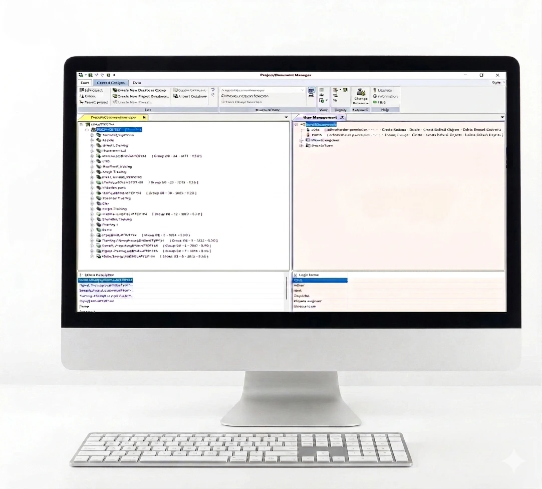
  • Includes integrated project and document management with configurable user rights, access control, and standardized templates to support multi-user engineering environments.
  • Provides built-in revision management where changes are marked directly in drawings, stored in the project database, and automatically reflected in title blocks and reports.
  • Maintains complete revision history with comments, version tracking, and notification functions to ensure controlled and traceable change management.
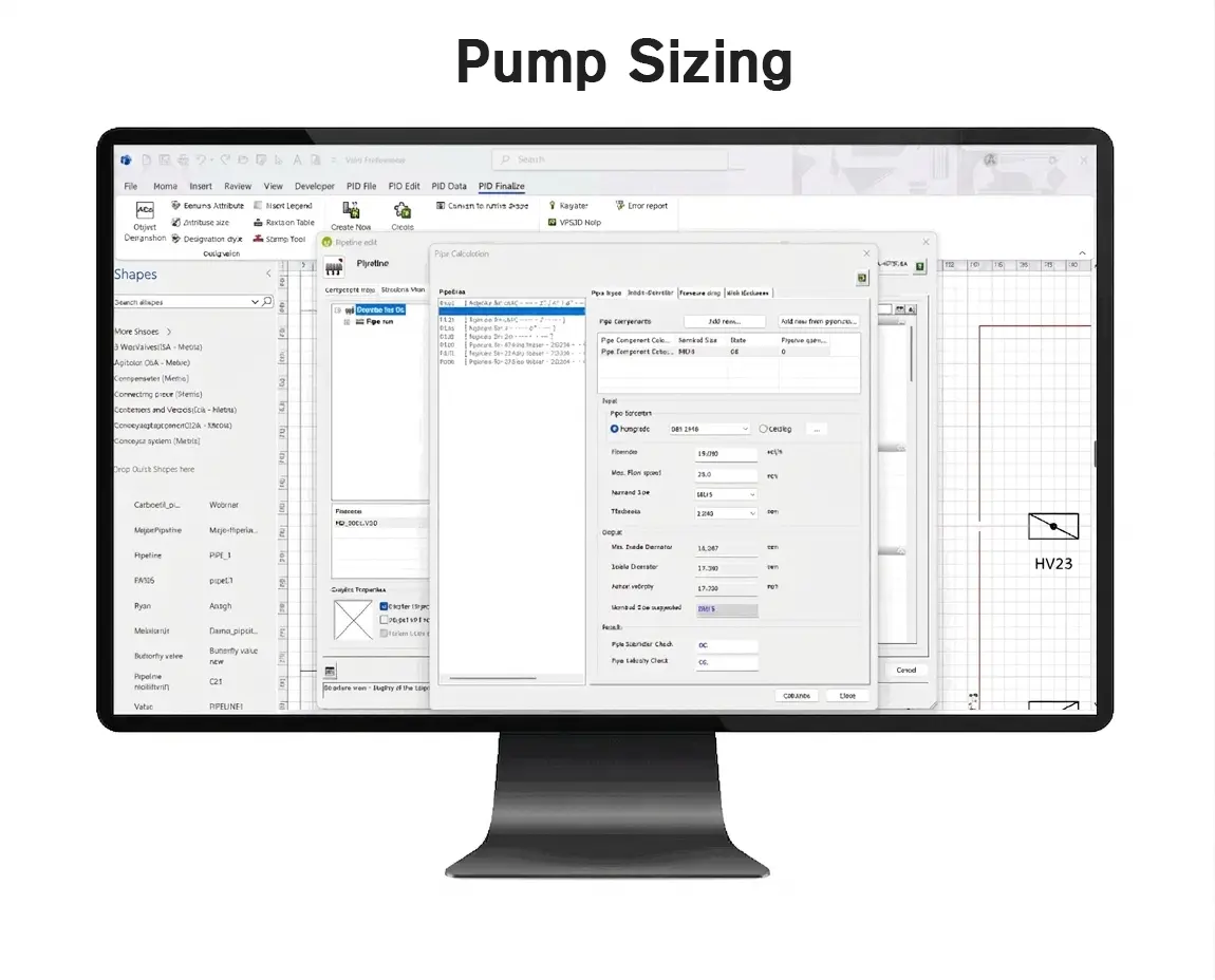
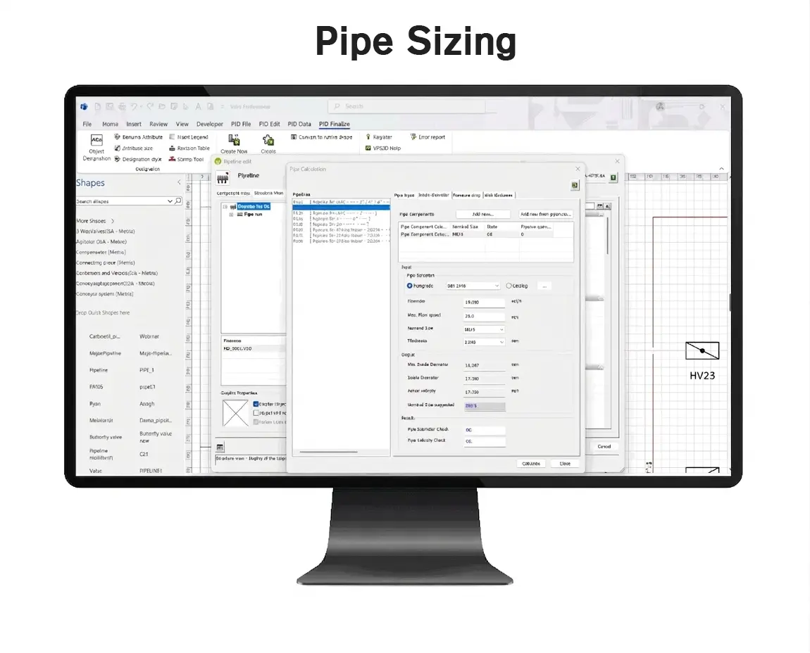
  • Pipe Sizing & Pump Sizing Calculations

  • The Pipe Sizing calculation focuses on Internal Diameter Calculation of pipe, Pipe Thickness Calculation and Pressure Drop Calculation using 'Resistance Factor' method
  • The User can determine the diameter of pipe based on flow and acceptable velocity of media
  • The User can also select an appropriate pump with 'Pump Sizing' feature, which is based on flow rate, total differential head, discharge static head, suction static head, frictional head losses, pump power parameters, etc.
  • Pump calculation automatically identifies suction and discharge side pipelines from P&lD based on the connection points