
 Deutsch
  English
 P&ID Standards for Oilfield Skid Packages: A Practical Guide for SME Operators
A choke manifold or a glycol dehydration skid rarely gets the engineering attention a refinery unit does. It ships pre-assembled, gets bolted onto a wellsite in a day or two, and is often installed from whatever drawing the equipment vendor emailed over. But the piping and instrumentation diagram (P&ID) for that skid still has to do the same job as one for a full plant: tell every downstream user — the technician isolating a pump five years from now, the contractor doing a tie-in, the safety officer reviewing a permit-to-work — exactly what's connected to what, and how to shut it down safely.
For SME oil & gas operators without a dedicated P&ID engineer on staff, that documentation discipline is the first thing to slip. Here's why skid packages need it anyway, where it typically breaks down, how to apply ISA-5.1 and PIP conventions to wellhead-specific equipment, and a checklist you can run against your next wellhead P&ID.
Why Skid-Mounted Packages Need the Same P&ID Rigor as a Major Plant
A skid looks self-contained. It isn't. A choke manifold, separator skid, or glycol dehydration package ties into the site's flowlines, instrument air, chemical injection, and emergency shutdown logic — systems that extend well past the skid rails and into the rest of the facility. This shows up constantly in SME operations, from onshore wellsites across Australia's Cooper and Surat basins to modular skids engineered and packaged through Singapore's EPC hubs before they ever reach site.
The P&ID is also the document everything else gets built on. Permit-to-work and lockout/tagout planning reference it to confirm isolation points. HAZOP and process safety reviews use it to trace failure paths. Commissioning teams check equipment against it line by line. Years later, whoever engineers a tie-in or an expansion starts from that same drawing. An error on a three-sheet skid P&ID propagates through every one of those processes exactly the same way an error on a two-hundred-sheet plant set would.
Scale cuts the other way too. Wellhead and choke manifold piping commonly runs at higher working pressures than the rest of a facility's process piping, so a missing tag or a misdrawn valve on a compact drawing carries outsized risk relative to its size. And a meaningful share of skid P&IDs arrive already drawn by the equipment vendor, in the vendor's own symbol set and tag format rather than the operator's. PIP's P&ID documentation criteria are explicit that they extend to P&IDs supplied by packaged equipment vendors, not only drawings produced in-house — because that handoff is exactly where drawings tend to drift from an operator's own standard.
None of this requires refinery-scale engineering headcount. It requires applying the same discipline consistently, on every skid, regardless of how small the drawing set is.
Common P&ID Documentation Gaps in SME Oil & Gas Projects
Three gaps show up on SME skid P&IDs more than any others:
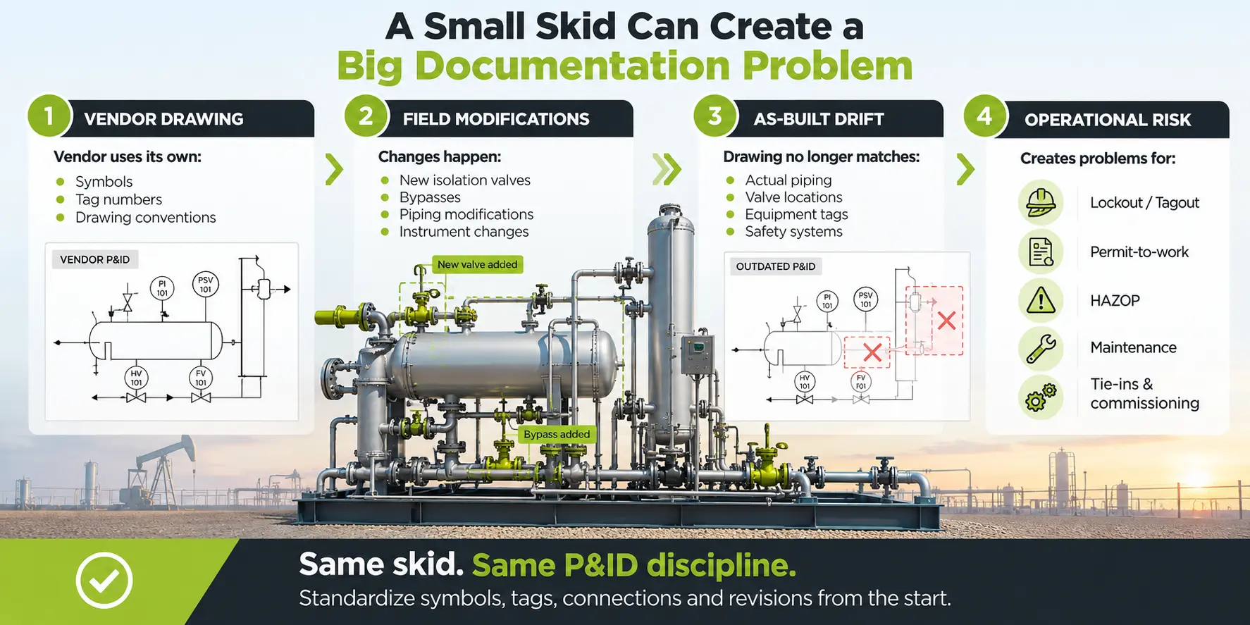
- Missing or unlabeled isolation valves. A valve gets added in the field — a temporary bypass that becomes permanent, a spare block valve fitted during a skid retrofit — and the drawing never catches up. The isolation plan built from that P&ID is now working from an incomplete picture of what's actually in the piping.
- Inconsistent tag numbering. The vendor's skid drawing tags a valve one way; the operator's asset register or CMMS references it another way; a tag gets reused across two different skids because "it's the same type of valve." A tag on a work order or a permit needs to point to exactly one physical valve — not send someone cross-referencing three documents to work out which one.
- As-built drift. The quiet version of the first two gaps: a field modification that never made it back onto the drawing. Individually minor, but it accumulates fast on a skid that's been field-modified a few times since commissioning, and nobody notices until an isolation plan or a HAZOP review turns up a valve that isn't where the drawing says it is.
All three share a root cause: no single person or system is responsible for keeping the drawing and the field in sync once the vendor's initial delivery gets filed away.
Mapping a P&ID Symbol Library to ISA-5.1 and PIP Conventions for Wellhead Equipment
Getting a wellhead P&ID to a consistent standard means working at three layers.
The instrumentation and general process layer. This is squarely covered by ISA-5.1, the ANSI/ISA standard for instrumentation and control symbols and identification. ISA updated the standard in 2024 and renamed it from "Instrumentation Symbols and Identification" to "Instrumentation and Control Symbols and Identification," making explicit that it now covers control symbols alongside measurement symbols. Outside North America, the equivalent is usually ISO 10628, which sets out general rules for how process-plant flow diagrams — including P&IDs — are prepared, so the same diagram reads consistently from initial planning through commissioning and eventual decommissioning, with a companion part covering the graphical symbols themselves. Most instrumentation on a wellhead skid — pressure transmitters, level switches, control valves — maps cleanly onto one of these.
The wellhead-equipment layer. This is where a standard symbol library runs out. Master valves, wing valves, swab valves, and fixed-versus-adjustable chokes aren't standard ISA-5.1 shapes — they're mechanical wellhead components, and most generic P&ID libraries either omit them or represent them too generically to be useful. The practical fix isn't waiting for a standard to cover them; it's extending your library with a purpose-built wellhead stencil, then tagging every symbol in it — mechanical and instrumentation alike — under one identification scheme, so a valve on the choke manifold and a transmitter three symbols away follow the same tag logic.
The format layer. ISA-5.1 and ISO 10628 govern symbols. Neither tells you how many equipment items belong on one sheet or which direction your process flow should run. That's what PIP PIC001, the P&ID documentation criteria maintained by Process Industry Practices, is for. Its formatting requirements include running primary process flow left to right across the sheet, bringing off-page connectors in on the left and out on the right, drawing primary process lines heavier than utility lines, and limiting a single P&ID to roughly three major equipment items so the sheet stays legible. Applying rules like these consistently — even to a two- or three-sheet skid package — is what makes a small drawing set read the same way a large one does, to anyone who picks it up.
A Practical Checklist for a Compliant Wellhead P&ID
Symbols
- Every symbol on the sheet comes from one library (ISA-5.1 or ISO 10628, plus a wellhead-specific stencil) no mixed conventions on the same drawing
- Fixed and adjustable chokes are visually distinguishable, not represented with the same symbol
- Vendor-supplied skid P&IDs have been checked, or redrawn, against your own symbol and tag convention before they're filed as the drawing of record
Tagging
- Every valve, instrument, and line carries a unique tag; no tag is reused across skids because the equipment "looks the same"
- Tag format matches your asset register or CMMS, not just the vendor's internal numbering
- Isolation valves are visually distinguishable from process and control valves at a glance
Isolation and safety
- Every physical isolation point in the field — including anything added after commissioning — appears on the drawing
- The isolation points named in your permit-to-work and lockout/tagout procedures are checked against the current drawing revision, not a superseded one Choke and kill lines, relief paths, and flare or vent routing show direction of flow
Documentation
- The sheet follows a consistent format: flow left to right, off-page connectors labeled, a manageable number of major equipment items per sheet
- Revision history is current, and the field copy matches the latest issued revision
- Valve and equipment lists are generated from the drawing data itself, not maintained separately in a spreadsheet that can drift out of sync
P&ID Standards for Skid Packages
Try it free on your next skid package and see whether it holds up against your own checklist.