
 Deutsch
  English
The Hidden Cost of P&ID Errors: How Small Mistakes Lead to Big Project Delays and Safety Risks
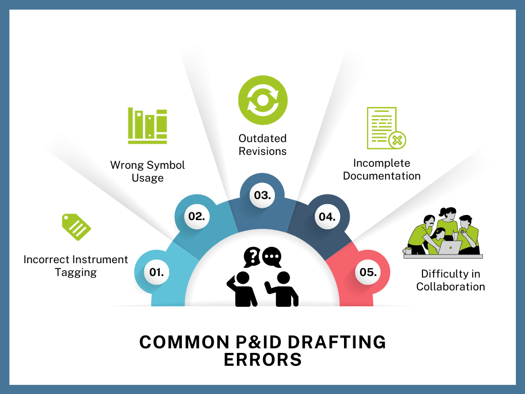
Common P&ID Drafting Errors
Even experienced engineers and designers can fall prey to subtle but impactful errors in P&IDs. Here are a few of the most frequent:.
- Incorrect Instrument Tagging : A wrongly labelled control valve or pressure indicator can lead to confusion during commissioning or operations, risking misinterpretation or incorrect connections.
- Omitted or Misconnected Lines: Missing pipelines or wrong line routing can result in process bottlenecks or operational failure, especially if discovered after procurement or installation.
- Wrong Symbol Usage : Using incorrect or non-standard symbols (e.g., representing a gate valve as a globe valve) can create inconsistencies that confuse both internal teams and external vendors.
- Outdated Revisions : Failure to update the latest changes in a centralized file can result in construction or maintenance teams referring to obsolete diagrams, leading to serious operational mismatches.
- Incomplete Documentation : Missing annotations, specification details, or legend keys make diagrams ambiguous and hard to interpret, especially for third-party contractors.

Preventive Steps to Avoid P&ID Mistakes
While some level of human error is inevitable, most issues can be proactively addressed through process, training, and tools.
- Standardization : Use industry-standard symbol libraries (ISA, ISO) to ensure consistency across diagrams and teams.
- Review & Approval Workflows: Establish multi-level peer review processes before finalizing any diagram.
- Centralized Documentation : Implement version control and centralized document management to keep everyone aligned with the latest revisions.
- Design Validation Tools : Adopt software that checks for broken links, duplicate tags, or missing connections to catch logical errors before they enter production.
How Visio P&ID Process Designer Helps Prevent P&ID Errors
As P&IDs remain central to process safety and efficiency, having the right tools like Visio P&ID Process Designer is no longer optional — it's essential. Visio P&ID Process Designer not only streamlines your design process but actively protects your projects from hidden risks through intelligent validation, automation, and collaboration features.
One of the standout features of Visio P&ID Process Designer is its built-in Logic Analyzer tool — a powerful asset for ensuring quality and consistency in your diagrams.
The Logic Analyzer doesn’t just highlight errors — it transforms how you track, review, and correct them:
- Pre-Defined Check Routines: Automatically validate your diagram against a range of industry-compliant checks like missing connections, duplicate tags, or undefined objects.
- Custom Rule Configuration : Add your own quality rules tailored to your engineering standards or client-specific requirements.
- Quick Navigation Across Projects: Easily locate and jump to any flagged error, object, or section of the drawing — significantly speeding up error resolution.
- Audit-Ready Validation Reports : Generate error reports for internal audits, approvals, or client handovers — ensuring transparency and trust.
Conclusion
With this level of built-in intelligence, Visio P&ID Process Designer becomes not just a drafting tool, but a quality assurance partner for your engineering team. Try Visio P&ID Process Designer Free and explore the intelligent way to create error free P&ID’s.