
 Deutsch
  English
 Why process engineers prefer Visio P&ID Process Designer over plain Microsoft Visio
For process engineers already working within Microsoft ecosystem, Visio P&ID Process Designer is compelling because it fills the biggest gap in native Microsoft Visio: turning simple diagrams into intelligent engineering documents.
Standard Microsoft Visio is effective for creating drawings. Visio P&ID Process Designer adds the engineering functionality that process engineers need.
1. It Keeps the Simplicity of Visio
Process engineers often need to:
- Develop and revise PFDs and P&IDs quickly
- Issue markups during design reviews
- Collaborate with operations, controls, and project teams
- Iterate during FEED and process optimization
- Update documentation throughout project execution
Instead of relying on manual drafting, disconnected spreadsheets, or overly complex plant-design systems, many teams prefer a workflow that combines intelligent P&ID functionality with the speed and accessibility of Microsoft Visio.
This is especially valuable for engineers who are responsible for process design and documentation but are not dedicated CAD designers.
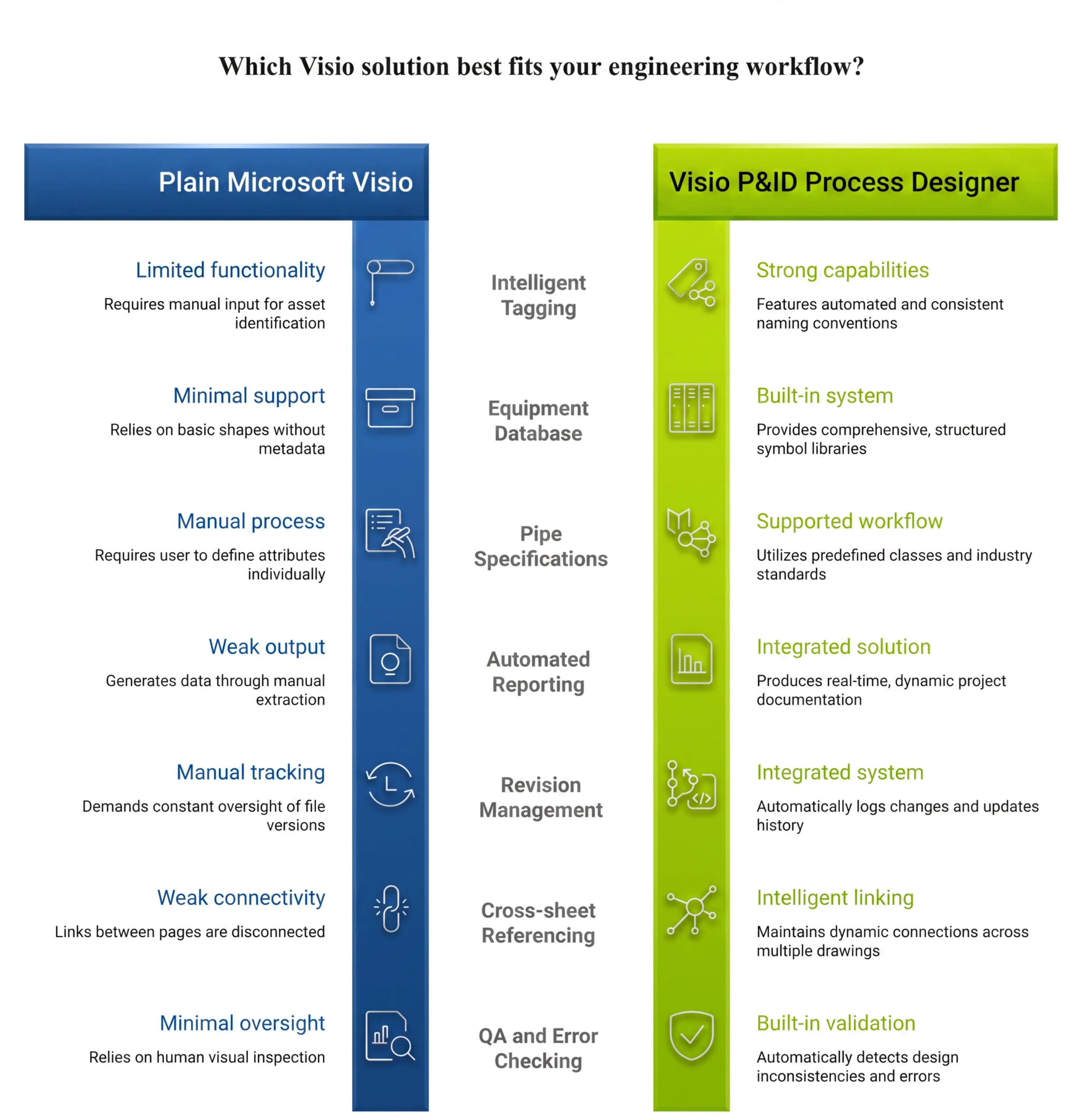
2. It Adds “Smart P&ID” Functionality Missing from Native Visio
Native Visio templates are primarily graphical. Visio P&ID Process Designer adds:
- Intelligent process symbols
- Centralized object data management
- Automatic tagging
- Spec-driven piping
- Document standardization
- Report generation
- Revision management
- Cross references
- Consistency and error checking
This helps improve engineering data consistency while reducing manual QA effort across drawing packages.
Examples include:
- Automatic prevention of duplicate valve or equipment tags
- Process consistency checks
- Process consistency checks
- Automated generation of equipment, valve, and pipeline reports
3. Process engineers live in Excel — and it integrates well
Many process engineering workflows still rely heavily on:
- Excel-based line lists, Datasheets, Equipment spec sheets, Vendor data
Visio P&ID Process Designer integrates well with these workflows through export/import support for:
- Excel, CSV, Word, PDF, DWG
For many engineering groups, this provides a practical middle ground between disconnected manual drafting and enterprise-scale database systems.
4. Well Suited for FEED and Conceptual Design
The platform is especially effective for:
- FEED packages
- Pilot plants
- Skid-mounted systems
- University & research projects
- Small-to-medium process plants
Process engineers frequently revise P&IDs during:
- HAZOP preparation
- Process optimization
- Control strategy development
- Proposal generation
- Client review cycles
Visio-based workflows allow engineers to iterate rapidly without requiring dedicated CAD operators.
5. Easier Collaboration Across Departments
P&IDs are reviewed by more than just process engineers. Operations, maintenance, controls, procurement, and management teams are often involved throughout project execution.
Because Visio is already widely recognized across industry, files are typically easier for non-CAD stakeholders to open, review, and annotate.
6. Strong standards support
The software includes libraries aligned with: ANSI, ISO 10628, IEC 62424, ISA-5.1 along with customizable libraries to support company-specific standards and drafting practices.
Where It Is Better Than Plain Visio
The Real Reason Process Engineers Prefer It
Visio P&ID Process Designer succeeds because it balances:
- Engineering intelligence
- Ease of use
- Cost
- Flexibility
- Office integration
For many process engineering teams, it delivers the core intelligent P&ID functionality required for daily engineering work without the overhead of large enterprise plant-design ecosystems.